6.2 KiB
title: Install Canoeboot HP Compaq Elite 8300 USDT x-toc-enable: true ...
PLEASE READ THESE INSTRUCTIONS BEFORE INSTALLING, OR YOU MAY BRICK YOUR MACHINE!! - Please click the link and follow the instructions there, before flashing. For posterity, here is the link again.
| Specifications | |
|---|---|
| Manufacturer | HP |
| Name | Compaq 8300 Elite USDT |
| Released | 2012 |
| Chipset | Intel Q77 |
| CPU | Intel Sandy/Ivy Bridge (65W max.) |
| Graphics | Intel HD Graphics or MXM graphics card |
| Memory | Up to 16GB (2x8GB) |
| Architecture | x86_64 |
| Intel ME/AMD PSP | Present, neutered |
| Flash chip | SOIC-16 16MiB |
Open source BIOS/UEFI firmware
This document will teach you how to install Canoeboot, on your HP Elite 8300 USDT desktop motherboard. Canoeboot replaces proprietary BIOS/UEFI firmware.
This is a small but powerful desktop using Sandy or Ivy Bridge CPUs (of up to 65W TDP). It has a slot for a discrete MXM graphics card as well. Some cards work while others don't. Your mileage will vary.
Canoeboot has support for this, in the Git repository and release versions after (but not including) 20230423.
These features are tested and confirmed working:
- Native raminit with both DIMMs (up to 2x8GB)
- Libgfxinit textmode and framebuffer on both DisplayPorts and VGA
- SeaBIOS and GRUB payloads
- External USB2 and USB3 ports: they all work
- USB 3.0 SuperSpeed on Linux-libre (rear, 4 ports)
- Ethernet
- Mini-PCIe WLAN
- SATA: 2.5" disk (6Gbps), mSATA (3Gbps), and optical drive bay
- PS/2 keyboard and mouse
- S3 suspend and resume, wake using USB keyboard
- Headphone output, line out, internal speaker
- Wake on LAN
- Rebooting
Disable security before flashing
Before internal flashing, you must first disable /dev/mem protections. Make
sure to re-enable them after you're finished.
See: Disabling /dev/mem protection
Install Canoeboot
These next sections will teach you how to install Canoeboot on your HP Elite 8300 USDT motherboard.
Internal flashing
Internal flashing is possible. OEM BIOS versions 2.87 and 2.90 are confirmed compatible with this guide. BIOS 2.05 is confirmed not to work.
If you have some other BIOS version, please do tell about it on IRC or comment on this issue, so this guide can be updated.
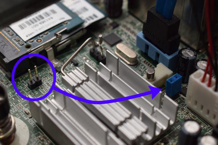
The jumper labelled "FDO" (for Flash Descriptor Override) needs to be shorted. That removes all write protections on this board.
We can borrow a shunt from another header on the board: PSWD. It is right next to the SO-DIMM RAM slots. Move it to the FDO header between the quartz crystal (small metal cylinder) and the power cable for the optical drive.
Boot into an OS of your choice (that has flashprog support).
The BIOS should no longer impose any write-protections.
You can now use flashprog -p internal freely.
Take a backup of the original BIOS:
flashprog -p internal -r oem_bios
If you are using the Canoeboot ROM images, the ME image is not provided and Canoeboot won't provide it. You avoid a brick by flashing around the existing Intel ME, to avoid a brick. Please read the guide:
How to avoid overwriting Intel ME
You can now flash canoeboot:
flashprog -p internal --ifd -i bios -w canoeboot.rom
If migrating from factory firmware (skip if migrating from Libreboot):
flashprog -p internal --ifd -i fd -w canoeboot.rom
Optionally re-flash the GbE region:
flashprog -p internal --ifd -i gbe -w canoeboot.rom
You can now move the jumper back to its original place. By default, Canoeboot applies no write-protection, so updating it can be done without the jumper anyway.
External flashing
Please only flash the BIOS region; if migrating from Libreboot, you must skip
the IFD region. If migrating from vendor firmware, please also flash the IFD
region. Optionally change the GbE region. Use the --ifd option along with
e.g. -i bios to flash a specific region. DO NOT flash the entire chip, because
this would overwrite the Intel ME, thus bricking your mainboard.
Unbricking is possible by external flashing. You first need to remove the optical disk drive and 2.5" HDD/SSD and the metal bracket that supports them. This requires you to open one torx (T15) screw in total.
The SOIC-16 flash chip is located on the edge of the board near the group of yellow cubes. Follow the general SPI flashing guide.
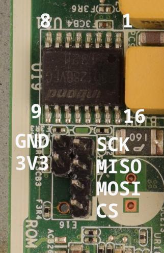
You might need to power the board by plugging it in. In that case, do not connect the Vcc (3v3) pin of the flash chip. Also make sure the board doesn't fully power on (that is, boot).
If you don't have a suitable clip, you can also use the ROM_RCVRY header right next to the flash chip. By default only the footprint is present, so you have to solder a pin header of your own. End result can be seen and the pinout can be seen in the photo earlier. Consult the HP service manual (page 241) on how to remove the motherboard from the chassis.
http://web.archive.org/web/20210305234331/https://h10032.www1.hp.com/ctg/Manual/c03612798.pdf
If you do this, you have to reapply thermal paste. That might be a good idea anyway, considering how old these are getting